2D Machining Strategies
A comprehensive suite of 2D machining capabilities comes standard with Prospector. For a more in-depth look at all the machining strategies and options available for each strategy, please review Machining Capabilities: An Overview.
Pocketing
-
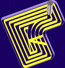
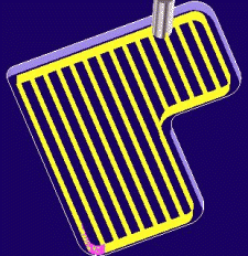
Zig-Zag and spiral clearing options.
-
Option to designate specific plunge point(s) for pre-drilled holes or off-the-block starts.
-
Unlimited number of islands and sub-pockets each with separate height/depth and draft.
-
Choice of contour or helical ramp or specify off the part or pre-drilled holes for Z-level transition.
-
Cusp height of fixed step down option.
-
High speed machining option to smooth interior corners.
Profiling
-
Full complement of cutting styles to address open and closed conditions.
-
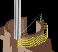
Variable radius circular leads for smooth lead-in and lead-off of the part.
-
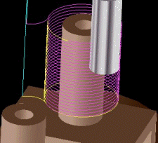
Multiple passes option to walk the cutter into the stock.
-
Overlap and extension option to maintain sharps and prevent cusp formation.
-
Cusp height and fixed step down.
-
Radial cutter compensation (G41/G42) with optional lead-in approach.
-
Option to designate specific plunge point(s) for pre-drilled holes or off-the-block starts.
-
Option for sharp corners to prevent the tool from rolling around exterior corners of a profile.
Face Milling
-
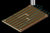
One-way or zig-zag cutting style.
-
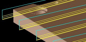
Step-down feature for multiple passes. Step down for final pass configured separately to produce the best finish possible.
-
Cut direction and start quadrant controls.
-
Configurable lead-in and lead-out distances from the part.
Chamfer Milling
-
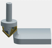
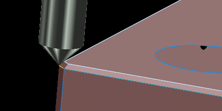
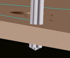
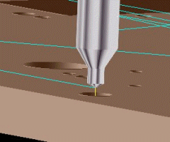
Automatic identification of chamfers features when machining from a solid model.
-
Machine from features or use 3D or 2D wireframe data.
-
Optional multiple passes to remove heavy stock. Separate last pass step-over for a smooth finish.
-
Optional circular lead-in and lead-out.
-
Starting point may be specified by the user.
-
Programmable tool tip offset to ensure complete machining of the chamfer.
-
Available left/right cutter compensation.
Thread Milling
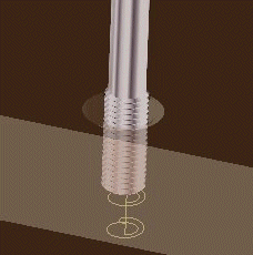
An alternative to tapping that can be particularly useful in cases where larger diameter holes are involved or when working with difficult materials. Other benefits include:
-
Produces threads with excellent form, finish, and dimensional accuracy.
-
Eliminates the possibilities and consequences of tap breakage.
-
Precise thread depth control.
-
One tool for through or blind holes.
-
One thread mill can produce varying thread diameters of the same pitch.
-
Smaller machines can produce larger threads because less spindle torque is needed.
-
No reversal of the spindle required.
-
Support for NPT/NPTF and UN/UNC/UNF threads.
-
Support for multiple passes to to walk the cutter into the stock to form the thread for very hard materials.
-
Radial cutter compensation (G41/G42) support.
-
Configurable helical lead radius and angle.
-
Optimized sorting of multiple holes to minimize machine time.
-
Option to machine top-down or bottom-up.
Helical Drilling
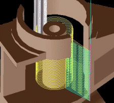
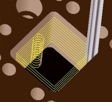
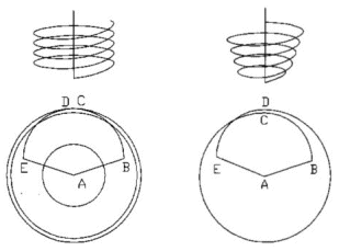
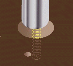
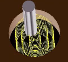
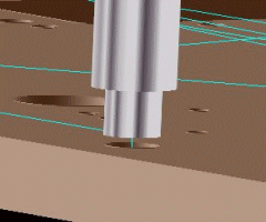
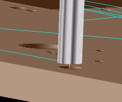
Helical drilling is a machining strategy for making holes with milling cutters. This is a useful machining technique for creating larger size holes where the use of large drills may not be appropriate due to the hardness of the materials o because of insufficient machine horsepower. Holes are created by one or more sets of concentric helical cutter paths.
-
Options for straight or drafted holes.
-
Optimized sorting of multiple holes to minimize machine time.
-
Configurable step down and step over.
Hole Making Operations
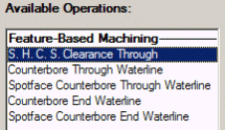
Comprehensive Suite of Operations:
|
Tooling Database Support for Tool Types:
|
-
Optimized sorting of holes to minimize machine time.
-
User-specified sorting (X-major, Y-Major, +X, -X, ...)
-
Full canned cycle support (G81, G82, G83, G84, G85, G86, G87, G88, G89).
-
Optional non-canned cycle output.
-
Fixed or optimized clear plane.
-
Configurable dwell time.
-
Full or partial retract option for peck drilling.
-
Rigid tapping option.
-
Configurable peck depth with optional peck depth reduction.
-
Full diameter depth specification option where applicable.
-
Configurable clear distance to stop short of the part before feeding in.
Gun Drilling
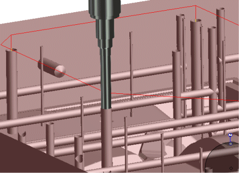
This specialized drill program for water systems allows for full control over all phases of the machining operation
-
Approach Phase -The approach phase advances the tool into the hole at a specified feedrate by the programmed approach distance you specify. The programmed approach distance can be zero if this phase not required. The spindle may optionally be started during the approach phase. There is a separate spindle speed you set for this phase of the program.
-
Engagement Phase - The engagement phase is the initial cutting phase. The coolant is turned on. The spindle is started at a programmed rate for this phase of the operation. By default it is 50% of the programmed spindle speed associated with the tool however you can set this to be a specific speed or program a different rule in PowerSource Insight. The tool feeds into the hole at a separately programmed feed rate. By default the feed rate is 50% of the programmed feed rate for the tool. Like the spindle speed, this feed rate can be modified however you wish. The tool continues to advance into the hole by the initial depth distance set for the program.
-
Drilling Phase - Spindle speed and feed rate is increased to the speed and feed programmed on the tool selection page. Tool advances into the hole until the full depth is achieved.
-
Disengagement Phase For Blind Holes - The tool is disengaged from the material by retracting a small incremental distance you specify from the bottom of the hole. The coolant is then turned off and the spindle is stopped.
-
Disengagement Phase For Through Holes - A breakthrough distance is specified which is added to the depth of the hole so that the tool completely breaks through the workpiece. Once through the workpiece, the coolant is turned off and the spindle is stopped.
-
Retract Phase - With the spindle stopped and coolant turned off, the tool retracts at the retract feed rate to the top of the hole. Once there, it will rapid to the drilling retract plane and repeat the drilling process for the next hole.
Feature-Based Hole Making
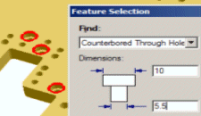
Feature-based hole making identifies 2D or 3D hole types in the job. The set of programs to fully machine the feature are automatically generated based on a predefined set of rules defined in the PowerSource database.
2D Part Data Feature Recognition:
|
3D Solid Model Feature Recognition
|
-
Automatic depth calculations for 3D features.
-
Optional layer and color filters assist locating features.
-
Graphic verification of feature selection.
-
Tool changer support option when programs are combined.

