Prospector 2015 Release Summary
Click here to open a printable version of this release summary as an Adobe PDF document.
Overview
Prospector 2015 is a major release that includes significant enhancements as well as customer requested software modifications and corrections. This release summary describes the software changes.
Platform Support
The table below lists the supported operating systems for Prospector 2015:
Operating System |
Revision Level |
Windows 10 |
All |
Windows 8.1 |
8.1 and 8.1 Update |
Windows 8 |
All |
Windows Server 2012 |
R1 & R2 |
Windows 7 |
Service Pack 1 |
Windows Server 2008 R2 |
All |
Windows XP and Windows Server 2003 are no longer supported. This means that the quality assurance testing was not performed for these operating systems. While no longer supported, there is nothing to prevent you from continuing to install and run the software on these operating systems. Any problems with the installation or execution of the software on these platforms will not be addressed in an update or future release.
If you are running Windows 8 and/or Window 8.1, we strongly encourage you to upgrade to Windows 10. The vast majority of the customer base did not opt to upgrade to either of these operating systems. Therefore, we may choose to drop formal support prior to the next release.
About Windows 10
Windows 10 is a new supported platform for the 2015 release. The 2015 release has been put through the full regimen of QA testing. This testing always done prior to a release on all supported platforms to ensure compatibility.
The previous release – 2014 – appears to function properly on Windows 10. This is because Windows 10 is largely a cosmetic change to Windows 8.x to correct deficiencies in that operating system that prevented it from being widely adopted. Internally the Windows 10 presents itself to the application software as being the Windows 8.1 operating system. Therefore, the 2014 releases are “fooled” into thinking they are running on Windows 8.1. If you experience any problems with the 2014 (and of course 2015) release with installing or running on Windows 10, please contact AMT Software customer support to report the issue(s).
3D Remaining Stock Model
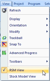
If you have the RSM View (Remaining Stock Model View) enabled in the View menu, when a new 3D program is created the 3D view itself will be modified to color the 3D model according to the current state of the remaining stock.
|
|
|
RSM View must be enabled in the View menu. |
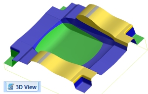
The 3D View will recolor the 3D model according to the current state of the stock and the position of the slider controls on the first page of the new 3D program wizard. A separate RSM View tab is not added. |
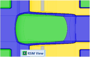
In previous versions, a separate RSM View tab was added. The computer-generated image showed the stock condition as though looking down the tool axis at the model. This representation was a 2D image that could not be rotated. |
The 3D RSM requires OpenGL Hardware Accelerated Graphics to be enabled in the Tools/Settings/Display property sheet:
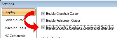
If OpenGL graphics is not enabled, the traditional RSM View tab will be calculated and presented just like in all previous versions of Prospector.
Gun Drilling Machining Strategy
Gun drilling is a new machining strategy for holemaking operations. The gun drilling strategy consists of the following sequence of phases:
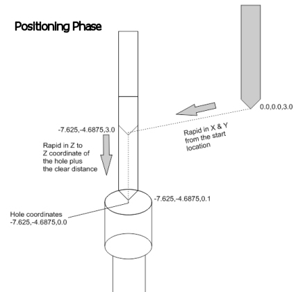 Positioning Phase - At rapid traverse the tool moves in X & Y from the home position to the X/Y coordinates of the hole location. A second rapid traverse move down in Z to the Z coordinate of the hole plus the programmed clear distance. This is the same sequence as any drilling operation except that neither the spindle nor coolant will be started at this stage of the operation. |
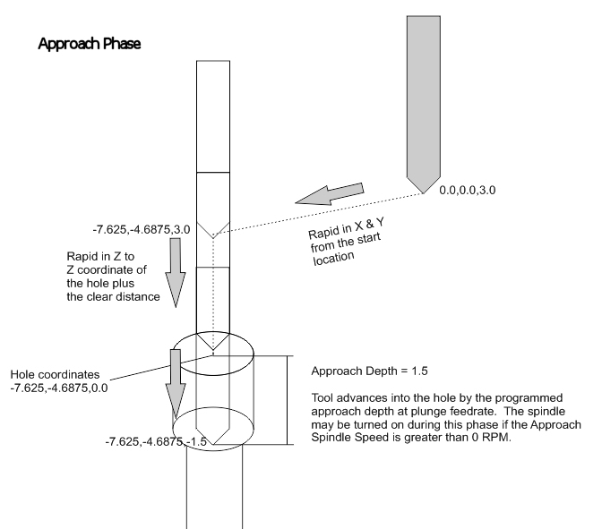
Approach Phase - The approach phase advances the tool into the hole at a specified feedrate by the programmed approach distance you specify. The programmed approach distance can be zero if this phase not required. The spindle may optionally be started during the approach phase. There is a separate spindle speed you set for this phase of the program. |
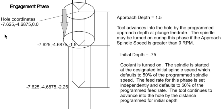
Engagement Phase - The engagement phase is the initial cutting phase. The coolant is turned on. The spindle is started at a programmed rate for this phase of the operation. By default it is 50% of the programmed spindle speed associated with the tool however you can set this to be a specific speed or program a different rule in PowerSource Insight. The tool feeds into the hole at a separately programmed feed rate. By default the feed rate is 50% of the programmed feed rate for the tool. Like the spindle speed, this feed rate can be modified however you wish. The tool continues to advance into the hole by the initial depth distance set for the program. |
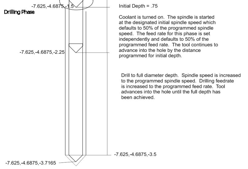
Drilling Phase - Spindle speed and feed rate is increased to the speed and feed programmed on the tool selection page. Tool advances into the hole until the full depth is achieved. |
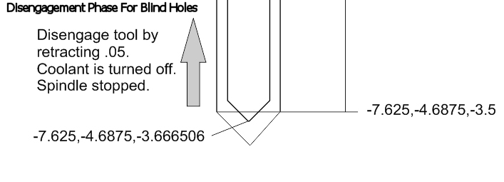
Disengagement Phase For Blind Holes - The tool is disengaged from the material by retracting a small incremental distance you specify from the bottom of the hole. The coolant is then turned off and the spindle is stopped. |
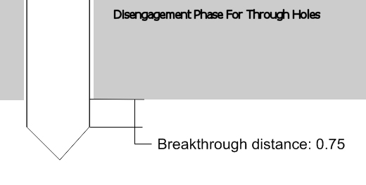
Disengagement Phase For Through Holes - A breakthrough distance is specified which is added to the depth of the hole so that the tool completely breaks through the workpiece. Once through the workpiece, the coolant is turned off and the spindle is stopped. |
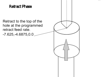
Retract Phase - With the spindle stopped and coolant turned off, the tool retracts at the retract feed rate to the top of the hole. Once there, it will rapid to the drilling retract plane and repeat the drilling process for the next hole |
Gun Drilling Programming in Prospector
Gun drilling programming is identical to conventional drilling for the first 4 pages of the new program wizard.
|
|
|
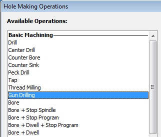
Choose Holemaking as the 2D Cutting Strategy on the first page. Select the holes on the Feature Selection page. Choose Gun Drilling on the Hole Making Operations page. |
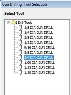
The Tool Selection page will show the gun drill tools in your tooling database. |
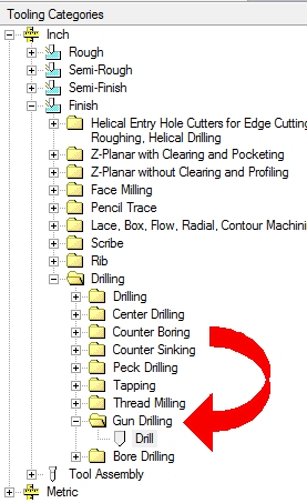
Note that gun drills are a new category of tools. In PowerSource Tooling you can create and edit gun drill tooling. |
|
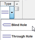
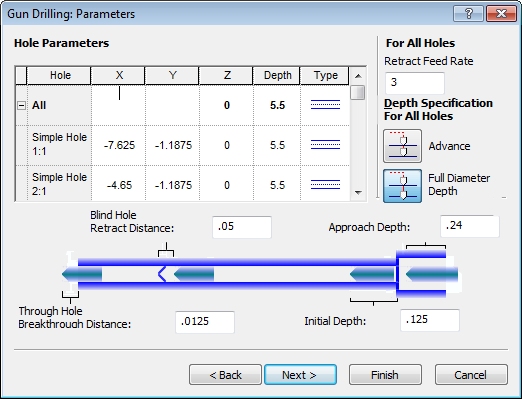
The Type column in the grid control specifies the type of hole being machined. The choices are either a blind hole or a through hole.Approach Depth is the distance to advance into the hole during the approach phase of the operation.Initial Depth is the distance to advance the tool into the hole during the engagement phase of the operation.Blind Hole Retract Distance is the distance to lift off the bottom of a blind hole during the disengagement phase of drilling a blind hole.Through Hole Breakthrough Distance is the distance the tool should advance further once the programmed depth is achieved during the disengagement phase of drilling a through hole. |
|
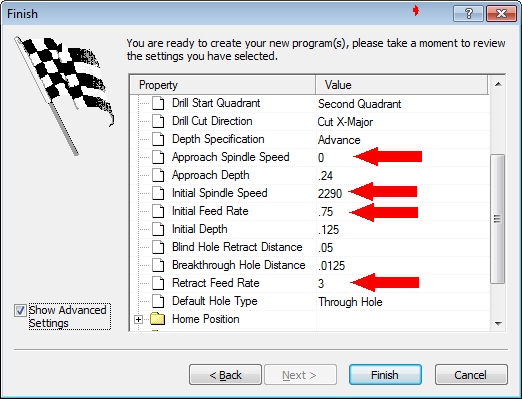
On the Finish page of the new program wizard, the spindle speeds and feed rates for the different phases of the machining operation can be specified.Approach Spindle Speed sets the spindle speed for the approach phase of the machining operation.Initial Spindle Speed and Initial Feed Rate sets the spindle speed and feed for the engagement phase of the machining operation.Retract Feed Rate sets the feed for the retract phase of the machining operation.Like all programs, these parameters can be established in your PowerSource database. Reasonable defaults based on the input feed rate and spindle speed set on the tooling page of the new program wizard are used however you are free to reprogram these on the finish page or more permanently in your PowerSource database using the PowerSource Insight program. |
Additional Hole Making Operations
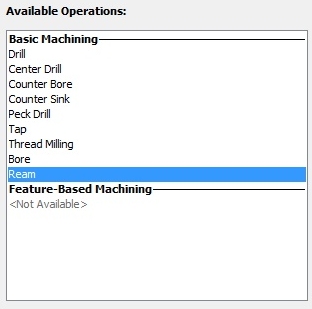
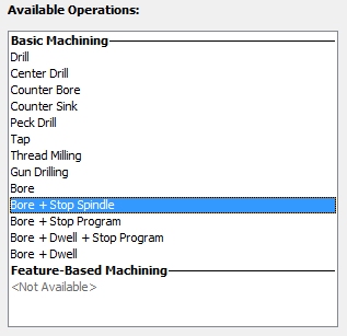
The Hole Making Operations page of the new program wizard has been revised to clarify the bore/ream operations.
|
|
Prior releases associated the G86 cycle with reaming. This caused some confusion in that this cycle can also be used for a boring operation. |
The revised operations page makes it clearer which operations are supported and what their function is. |
Operation |
Canned Cycle |
Function |
Bore |
G85 |
Rapid to the Z coordinate of the hole plus the clear distance. Feed to depth at the programmed plunge feed rate. Retract at plunge feed rate to the Z coordinate of the hole plus the clear distance. |
Bore + Spindle Stop |
G86 |
Rapid to the Z coordinate of the hole plus the clear distance. Feed to depth at the programmed plunge feed rate. Stop the spindle. Rapid retract in Z to the start of the operation. |
Bore + Stop Program |
G87 |
Rapid to the Z coordinate of the hole plus the clear distance. Feed to depth at the programmed plunge feed rate. Program stop. A G87 typically orients the spindle and moves off-center prior to what is either a manual retract or rapid retract to the Z coordinate of the hole plus the clear distance. Back boring is not (boring in the +Z direction) is not supported. |
Bore + Dwell + Stop Program |
G88 |
Rapid to the Z coordinate of the hole plus the clear distance. Feed to depth at the programmed plunge feed rate. Dwell for a specified number of seconds. Program stop. A manual retract or rapid retract to the Z coordinate of the hole plus the clear distance follows. |
Bore + Dwell |
G89 |
Rapid to the Z coordinate of the hole plus the clear distance. Feed to depth at the programmed plunge feed rate. Dwell for a specified number of seconds. Retract at plunge feed rate to the Z coordinate of the hole plus the clear distance. |
Tool categories for G85 - G89 cycles on the tooling page include both reamers and boring bars.
If your CNC does not support one or more canned cycles or you do not wish to use them, non-canned cycle output will be generated using the equivalent G-codes and M-codes to emulate the function of the canned cycle.
Adaptive Step Down for Z-Planar No Clear
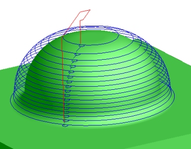
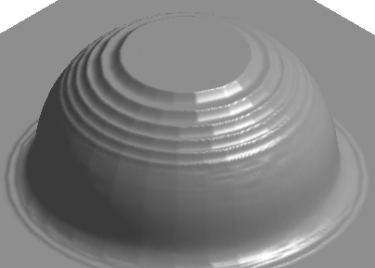
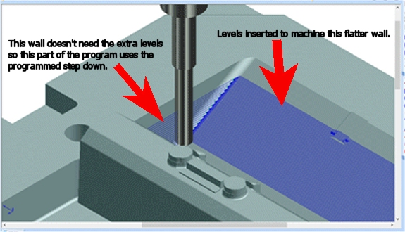
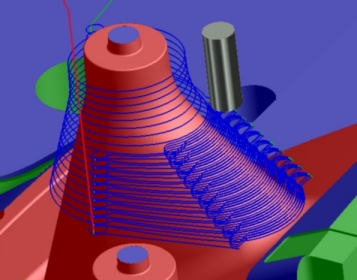
Adaptive step down reduces the programmed step down in areas where the part data flattens out which would cause relatively large cusps of materials to be left behind.
|
|
The example above shows how a fixed step down forces each level of the job to be the same distance apart. |
This results in relatively large cusps of material left behind in areas that are relatively flat. |
|
|
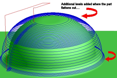
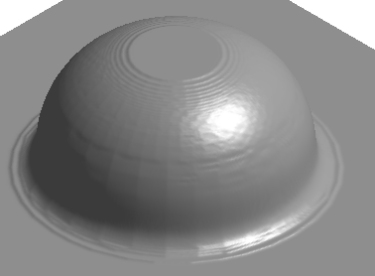
Adaptive step down adjusts the step down so that large cusps of material could remain. |
This results in a better finish and more efficient program because the step down is reduced only for those areas of the program that require it instead of having to use a small step down for the entire program. |
|
|
Extra levels are added only in those areas where a cusp might form. In the examples above, levels are added only in those areas of that require additional machining to mill the larger cusps that would be left behind. |
|
Adaptive step down is an advanced setting for Z-Planar No Clear programs that you can enable on the Finish page of the new program wizard:
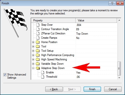
The Threshold value adjusts the sensitivity of the feature when detecting the buildup of a cusp. Smaller values will cause more levels to be inserted. Larger values will ignore smaller cusps of material.
Creating Planar Patch Surfaces
Patch surfaces are temporary surfaces to seal off features of the part you do not wish to machine initially or ever. Patch surfaces can be removed at a later stage of machining to get at the features they were concealing when it is time to machine them. In previous editions of Prospector, patch surfaces had to be created as part of the CAD data and identified by color and/or layer when the project was initially created. New for 2015 is the ability to develop patch surfaces from within Prospector for planar areas of the part. This typically works well for covering holes which will be machined later using hole making operations.
Prerequisite
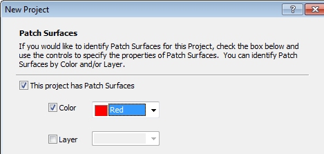
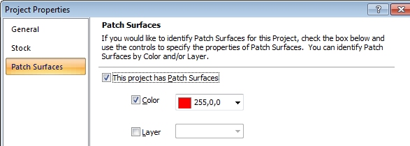
Before you can create patch surfaces, you must declare that the project uses patch surfaces. This can be done when the project is first created or afterwards in the Properties/Patch Surfaces property sheet for the project:
|
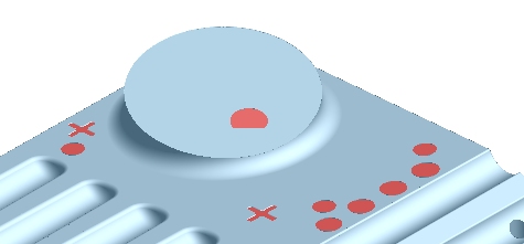
Declare the project will use patch surfaces at the time the project is created. In the example above, the project is created with patch surfaces enabled and the patch surfaces will be identified as those surfaces in red. You can also (or instead) put the patch surfaces on a separate unique layer number. |
|
After a project has been created, you can update the project by choosing Properties from the Project menu. Change to the Patch Surfaces property sheet and enable the patch surface feature and indicate how Prospector should identify a patch surface (i.e. what color and/or layer will patch surfaces be associated with). |
Creating Patch Surfaces
Once your project is setup to use patch surfaces, you can begin to identify areas where you want to patch.
|
|
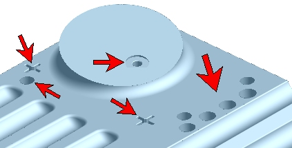
These areas of the job we don't wish to machine yet. We'll need to put patch surfaces over them so that these features are ignored during cutter path generation. |
Create profile(s) around each area to be patched. For each area to patch, the profile(s) must form a contiguous closed area and be on the same plane. Hint: Use Tools/Profile Tools/Extract Face Edges to develop the profiles you will need. Once you have developed the profile(s), make them selected. |
|
|
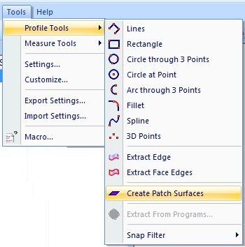
Choose Create Patch Surfaces from the Tools/Profile Tools menu. |
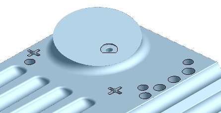
The results are shown above. Perfect. The planar patch surfaces covered the areas we don't want to machine yet. Note that the profiles and resulting surfaces need only be planar; they don't need to lie in a plane perpendicular to Z axis. |
This same functionality to create planar patch surfaces has been added to Prospector Design as well.
Z-Planar No Clear Ramp Descent
Z-Planar No Clear with the style set to Plunge Oneway No Lift has been enhanced to allow for the option to ramp in order to descend to the next level:
|
|
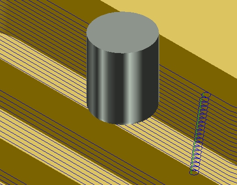
Without ramps, the tool will plunge to descend to the next level. All previous versions of Prospector used the plunge method. Above is a typical program that uses circular leads to move off the part, descend then lead back into the material and machine the level. |
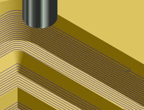
The new ramp method allows the tool to stay in contact with the work piece for the entire duration of the program. To descend to lower levels, the tool will ramp down as it machines the part until it reaches the proper Z-level. The ramp angle is a program parameter. |
|
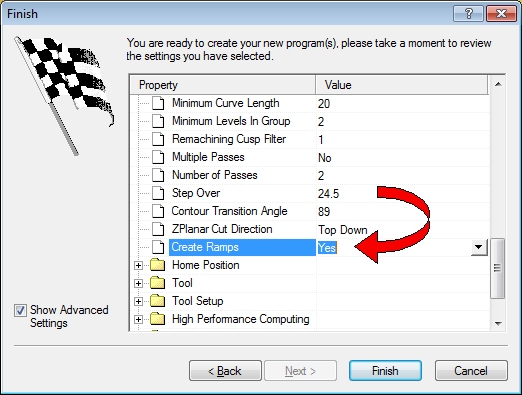
To enable ramping as the descent method, proceed to the Finish page of the new program wizard and set Create Ramps to Yes.The ramp angle may optionally be set on the finish page to establish the angle of descent to proceed to lower levels. |
The ramping method for descending to lower levels is only applied to areas of the program that form a closed cutter path. Machining around bosses or into a pocket are considered suitable for using ramps. Open areas like the corner of a lock or an open slot would not be assembled using the ramp method. Certain programs may go from an open condition to a closed condition because of the geometry of the part data. In these cases the closed areas would use ramps but the open areas would plunge.
Adding Tools to the Tooling Database On-the-Fly
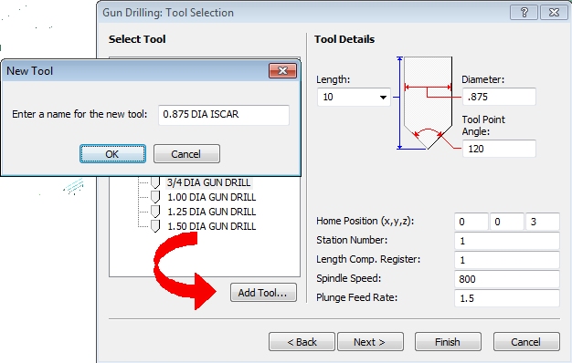
On the tooling page for the new program wizard, a button has been added to allow you to add a tool definition to your PowerSource database:
|
If you modify the parameter(s) for a tool, the Add Tool button will be enabled.Clicking Add Tool will cause Prospector to prompt you for a name for the new tool. Once you have assigned a name, click OK to add it to your PowerSource database.New tool definitions added via the Tooling page are put in the same bins as the current program. If it's an inch project, the tool is inserted for the inch database. The new tool definition is inserted into the same machining category you are currently programming (i.e. if you are programming Finish programs, the tool is inserted in only the Finish category). The new tool definition will go into the same machining strategy (e.g. if it's a drill, it will go into the collection of drills under Drilling). |
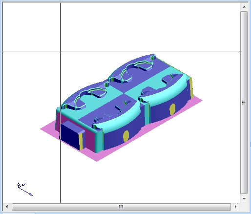
Shade and Wireframe View Option
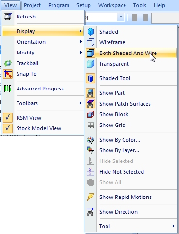
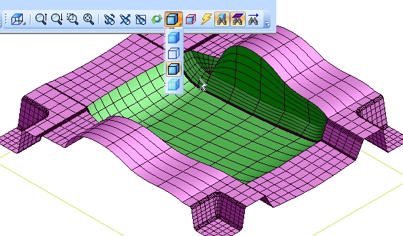
A new option has been added to Prospector to draw the model as a shaded image as well as the surface UV lines:
|
|
Choose Both Shaded and Wire from the View/Display menu. |
The surface flow lines are shown on the shaded image of the part data. The density of the flow line can be adjusted in the Tools/Settings/Display property sheet. Note that the toolbar consolidates the possible model view settings as a drop-down list if icons. |
Copy/Paste Tools in PowerSource Tooling
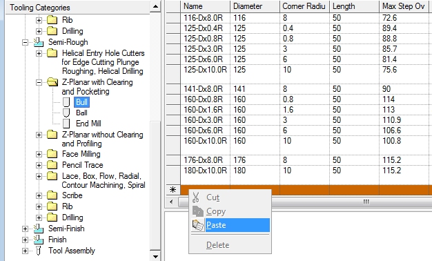
Adding tools to the PowerSource database with the Tooling application was a time consuming and sometimes aggravating affair because it was not possible to copy and paste multiple tools. For example, it you added several Bull cutters for Z-Planar With Clear/Rough and wanted to use these tools for Finish as well, it was not possible to copy & paste multiple tools from one category to another. Now it's possible:
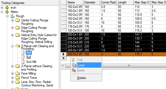
Open the category you wish to copy from. In this example it's Bull cutters for the Rough machining category that are designated for use with Z-Planar with Clearing and Pocketing machining strategies.
Multi-select the tools you wish to copy. Clicking in the selection column (left-most column) selects a tool. You can add to your selection using Ctrl+Click to add another specific tool to the selection or Shift+Click to add a range of rows to the selection.
In the example to the right, we selected all the cutters that are 200MM in diameter or larger.
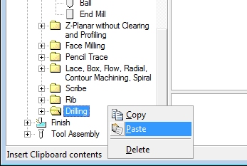
Right-click and choose Copy from the context menu or choose Copy from the Edit menu to copy the selected tools to the clipboard.
Change to the category and machining strategy where you wish to insert the tools just copied.
In this example, we changed to Semi-Rough and the same machining strategy - Z-Planar with Clearing and Pocketing.
Click the Add Tool (* in the left-most
column) and right-click to choose Paste from the context menu or use the Paste menu
item from the Edit menu.
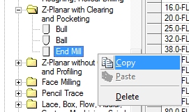
Copying All Tools of a Specific Type
|
|
In the tooling tree control, choose the tool type you wish to copy. Right click or choose Copy from the Edit menu. This will copy all tools of that type to the clipboard. |
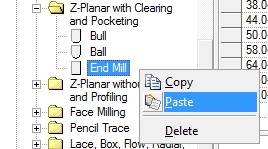
In the tooling tree control, choose the tool type and machining category where the tools you just copied are to go. Choose Paste from the Edit menu or right click and choose Paste from the context menu to insert the tools. |
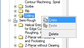
Copying All Tools for a Machining Strategy
|
|
In the tooling tree control, choose the machining category from which all the tools in that category you want to be copied to the clipboard. In the example above, we want all tools for all drilling operations from the Semi-Rough category copied (Drills, Center Drills, Boring Bars, ....). Right click and choose Copy from the context menu or choose Copy from the Edit menu. |
In the tooling tree control, choose the machining category into which you want to insert the tools you just copied. In this example, we'll put all the drilling tools from the Semi-Rough machining category into the Semi-Finish category by clicking on Drilling in the Semi-Finish category and choosing Paste from either the context menu or the Edit menu. |
Notes about copying tools:
All configurations associated with a copied tool are carried forward to where they are pasted.
If a tool of the same name already exists where a copied tool is pasted, you will end up with 2 tools of the same name.
Nonsensical operations are flagged as errors. For example, you would not be allowed to copy Ball cutters to a Center Drill category.
You cannot copy metric tools to inch tooling.
Can copy between 2 different sessions of Tooling. This is very handy when setting up a new tooling database by reusing some data from an existing database.
General Enhancements
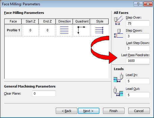
Face Milling
A different feed rate for the Last Pass of a face milling program can now be specified on the Parameters page for facemilling:
Persistent Geometry
Geometry created during a session of Prospector is now saved as part of the project data. In previous versions, any profiles you may have created during the session were discarded when the project was closed or the session ended.
Recent Projects Preview
The Recent Projects menu item in the File menu will now post a preview of the project when you track over a project in the list.
SolidWorks Project Creation Plug-in
The plug-in for SolidWorks has been revised to properly orient the design when a new project is created. Newer versions of SolidWorks changed how the model was oriented requiring an update to the plug-in to handle the newer versions.
Scribe as a 2D Machining Strategy
Scribe is now available as a machining strategy for both 3D and 2D machining. In previous releases, scribe was only available as a 3D machining strategy. Because scribe does not rely on 3D methods for program generation, it will appear as a strategy for 2D and 3D machining.
Fullscreen Cursor Display
A new option in the Tools/Settings dialog allows for the display of a “cursor” that extends to the extents of the current view in X and Y:
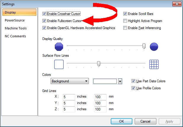
Enable Fullscreen Cursor produces this as a display:
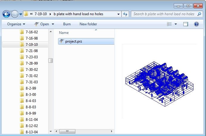
Integration with Windows Explorer
A preview picture of the project (.prj or .prz file) will be shown in the preview pane in Windows Explorer and the File/Open dialog:
Corrections and Maintenance
After a Z-Planar With Clear program was generated with Machine Floors set to Insert Levels At Floor, updating the program to Floors Only could cause the program to fail to generate.
Prospector Design has been modified to be able to handle very old Prospector projects. The previous release would fail to recognize very old projects as being valid projects.
The High Speed Machining option for adding arcs to interior corners of a Z-Planar programs has been revised to ensure that the arcs are inserted consistently and that their insertion will not cause standing stock to remain after the level is cleared.
If an incorrect value is entered for the End Z of a program (e.g. End Z higher than the Start Z), an error dialog is posted and the previous End Z value is reinserted into the dialog. Previous versions would retain the improper value and stymie the user from using the Back button on the new program wizard.
Error handling when a part data file that is not in a format suitable for Prospector is selected when creating a new project has been improved. Upon selection of a part data file, the format of the file will be inspected immediately and if it is not a supported format, an error dialog will be posted.
When a Chain operation is chosen, the cursor will change to the 'pick' cursor to give a clear indication that "it's your turn" to choose a profile to begin the chaining. Other modal tools that require a user to pick an item have been similarly updated to change the cursor to indicate a selection is required.
When creating projects with Parasolid part data files, the correct tolerance will be used when the file is imported. Previous versions used a tolerance that was 10x too small which could cause programs to fail to generate and/or take an excessive amount of time to build.
The default for the Project Based method of handling Prospector projects will show only local projects in the Open dialog. Previous versions displayed both remote (archived) projects and local projects. When you choose a display option in the Open project dialog (Local Only, Remote Only, Both Local and Remote), the setting is remembered for the session and for future sessions of Prospector.
Resolved Incident and Enhancement Report
When you report a problem or request an enhancement by contacting our customer service team or reporting a problem at the web portal AMT OnTime you will receive a unique ID for each problem and/or requested enhancement. When we complete a release all incidents and enhancements that were addressed for that particular release are assigned a closed status. The following table lists the closed records for this release.
Record ID |
Customer |
Synopsis |
AMT00039 |
AMT |
Add a preview image when the cursor hovers over an item in the File/Recent Projects menu. |
AMT00096 |
AMT |
Screen cursor disappears after contact is made to a touch screen. |
AMT00168 |
AMT |
Order of the machining strategies on the advanced wizard page is not consistent with the conventional wizard. |
AMT00229 |
AMT |
Implement a new license enforcement technology for licensing a 30-day evaluation. |
AMT00255 |
Oakwood |
Add the ability to create patch surfaces in Prospector. |
AMT00260 |
AMT |
Post an error dialog immediately if the part data file chosen for a new project is not a data format that Prospector accepts. |
AMT00261 |
Vobeda |
Add the ability to create patch surfaces in Prospector. |
AMT00266 |
AMT |
Revise the plugin to SolidWorks to allow a project to be created as a file-based project or project-based project. |
AMT00285 |
AMT |
When using the editing feature Chain Profiles, the cursor should change to the indicate cursor to clue the user that the next step is to pick a profile to begin chaining. |
AMT00287 |
JO-AD |
Switching from "Machine Floors" to "Machine Floors Only" for this Z-Planar With Clear program causes the program to fail to generate. |
AMT00304 |
Kent Tool & Die |
If a project is using patch surfaces, windows created for machining can appear to be shifted out of position when in the RSM view. |
AMT00307 |
AMT |
Revise Prospector Design so that it can open very old Prospector projects without errors. |
AMT00308 |
AMT |
Revise Prospector Design so that the F1 key causes the help to be displayed. |
AMT00309 |
AMT |
If an incorrect value is entered for the End Z of a program (e.g. End Z higher than the Start Z), automatically reset the End Z to the original value when the user clicks OK in the message box displaying the error message. |
AMT00310 |
AMT |
Prospector will crash if you click on the Zoom Scale on the Status Bar. |
AMT00311 |
ITW Drawform |
The plugin for SolidWorks is creating projects with the part data incorrectly oriented. |
AMT00313 |
AMT |
Lace cut program is skipping in certain areas inside the window. |
AMT00314 |
AMT |
If an IGES file has invalid or nonsensical entities, Prospector does not respond properly and is not allowing the data file to be changed. |
AMT00317 |
AMT |
The parameters dialog for 2D profiling is not displaying the stock allowance control correctly when cutting 'On' the profile. |
AMT00318 |
AMT |
Update the Help/Prospector On The Web menu to link to the correct pages of the revised ProspectorNC.com website. |
AMT00320 |
Kent Tool & Die |
This lace cut program is only cutting a portion of the entire window. |
AMT00321 |
Global Source Mfg |
The Maintain Sharp Edges option for this lace cut is not being honored causing the program to gouge the part. |
AMT00322 |
AMT |
If the a program is active and you choose Properties for the current setup, when the dialog is closed the tool display is corrupted. |
AMT00323 |
Mangas |
Add the ability to Copy/Paste multiple tools in PowerSource Tooling |
AMT00324 |
MSI Mold Builders |
The High Speed Machining option for adding arcs to interior corners of a Z-Planar program is not consistently adding the arcs for this program. |
AMT00325 |
MSI Mold Builders |
If the Filter Surface option is enabled, using this IGES file as part data is generating an error during the filtering phase of project creation. |
AMT00326 |
MSI Mold Builders |
This Z-Planar program is incorrectly skipping to a lower level of the program before returning to the correct level to continue machining. |
AMT00327 |
AMT |
Prospector project data is being corrupted in the case where the Filter Surface function failed. |
AMT00328 |
MSI Mold Builders |
HSM option for interior corners is incorrectly placing the arcs for clearing cuts such that standing islands of stock are being left behind. |
AMT00330 |
AMT |
On Project/Open, give focus to the grid control to make it quicker to choose the project to open. |
AMT00331 |
gromaTec |
Provide an option for face milling to specify a different feed rate for the last pass. |
AMT00334 |
Global Source Mfg |
Add the ability to display the part data shaded with the wireframe and surface UV lines. |
AMT00335 |
Global Source Mfg |
Add the ability to create patch surfaces in Prospector. |
AMT00336 |
AMT |
This Z-Planar With Clear program is not cutting to the full depth of the pocket. |
AMT00339 |
MSI Mold Builders |
Revise the hole making strategy page of the wizard to be clear about what the strategy is and what it will do. |
AMT00340 |
AMT |
Add support for the canned cycles G87, G88 and G89. |
AMT00344 |
AMT |
The Scribe machining strategy should be available as a 2D machining strategy. |
AMT00347 |
AMT |
Insert levels into Z-Planar No Clear programs when areas of the program flatten out and leave behind larger cusps of material. |
AMT00348 |
AMT |
Add the ability to ramp for Z-Planar No Clear when machining closed areas. |
AMT00359 |
AMT |
Assign surfaces unique names in the event they do not have a name or ID. |
AMT00360 |
AMT |
Not all surface colors are shown in the list of colors for identifying patch surfaces. |
AMT00363 |
AMT |
Add a warning symbol overlay to the project icon in the program list control if the project has design defects. |
AMT00365 |
AMT |
Remember the file filter (*.pdb, *.igs, ...) for the Open dialog when choosing part data for a project. |
AMT00376 |
AMT |
Changing the draft of an island inside a pocket that also includes a sub-pocket will incorrectly change the draft of the sub-pocket as well for 2D pocketing. |
AMT00407 |
AMT |
In PowerSource Tooling the Tool/Assembly Configuration properties won't display when you click in a cell and then click back on the item. |
AMT00422 |
Grand Traverse |
Parasolid part data is preventing this program from generating. |
AMT00423 |
Grand Traverse |
Default the Open project dialog to local jobs. Remember the last setting as well. |